An Introduction to Structural Geology
About the author

Jon
University of Edinburgh
Introduction
Structural geology is the study of the features formed by geological processes. Features include faults, folds and dipping strata. Geologists can work out the order of events and see which events are related by taking fairly simple measurements and using simple methods.
Measurements and Techniques
The most obvious thing to do when trying to decipher the structural history of a formation is to describe it. One way of doing this is to measure the dip and strike. The dip is the amount a bed of rock is tipped from the horizontal. The strike is the direction which is ninety degrees from the dip, i.e. along the horizontal line on the bed. The strike can be in two directions, hence the dip could be in one of two directions also. There is a convention for the strike to be the in the direction you are facing if the rocks are dipping to your right. Some geologists prefer to measure the dip direction, rather than strike, as it is slightly simpler. However, all maps use dip and strike, not dip direction.
This is complicated slightly by apparent dip. This is due to the fact that you are not always looking edge on (perpendicular) to the bed you are measuring. If you are looking at a bed at a slight angle, then you see the apparent dip. The true dip will be greater than the apparent dip, as it is the maximum amount of dip, so the apparent dip can appear to be anything from 0° to the maximum (true) dip.
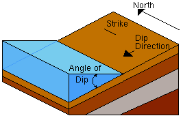
Figure 1: Dip and strike of a bedding plane.
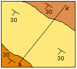
In this diagram, the dip is 30°, with a strike north/south (0°/180°), the dip direction is 270°. On a geological map, symbols are used for the dip and strike. The strike is represented by a bar, and the dip by a mark on the strike bar on the downdip direction with the dip written alongside, as shown on the map below left.
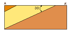
A geological cross section can be drawn from the map showing the subsurface structure. Obviously, only features which can be seen on the surface can be represented. The cross-section below right is drawn using the values in the map alongside.
 |
 |
|
Figure 2a: A geological map |
Figure 2b: A cross section of the map |
A technique which is used often is to plot values of dip and dip direction on a stereogram. A stereogram (or stereonet or hemispherical projection) is a way of representing 3-dimensional directions on a 2-dimensional surface. The net is a projection from the point onto the equator. A net is shown below.
The mechanisms of plotting points is shown in the next 4 diagrams.
1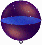 |
2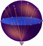 |
|
The points are placed all around the sphere representing 3D space. |
The points are projected down onto the equatorial plane on a line which meets up at the south pole |
3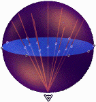 |
4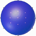 |
|
The points are then "moved" onto the plane, which is your stereonet |
The final stereonet. |
To plot a bed onto the stereonet, use the following guide.
- Put tracing paper on stereonet
- Draw around the circumference (known as the primitive circle or equator), and mark on North (and maybe South)
- To plot a point with a 30° dip in a direction of 130°, (written 30/130) plot a point on the equator 130° around
- Then rotate the tracing paper so that the point you've just plotted lies at 90°
- Then counting 30° in from the edge mark a second point. This is the point 30/130
A similar method is used to plot a pole to bedding, that is, a line which is perpendicular to the bedding surface.
- Put tracing paper on stereonet
- Draw around the circumference (known as the primitive circle or equator), and mark on North (and maybe South)
- To plot a pole to a bed which is dipping at 30°, in a direction of 130°, (written 30/130) plot a point on the equator 130° around
- Then rotate the tracing paper so that the point you've just plotted lies at 90°
- Then counting 30° out from the centre to the opposite side to your first point, mark a second point. This is the line perpendicular to the plane dipping 30/130
On a stereonet a line is represented by a point and a plane by a line.
Folds
Folding of rocks is caused by the compression of rocks. This occurs slowly, over a long period of time. If this happened quickly, the rocks would break, and fault. This is due to the mechanical properties of rocks, namely it's plastic nature. If a rock is stretched slowly, then it will behave in a ductile fashion. If stretched quickly, the rock behaves in a brittle fashion. This behavior can be mimicked by using Blu-Tac. A typical fold is shown below, outlining the terms used in describing folds.
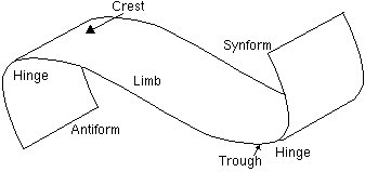
Figure 3: Nomenclature used when describing folds
- Hinge:
- Where curvature of the fold is at a maximum
- Crest & Trough:
- Where fold surface reaches a minimum and maximum respectively
- Limb:
- Beds between two hinges
- Antiform & Synform:
- Convex upwards or convex downward folds respectively
- Anticline & Syncline:
- Older or younger beds at the core respectively. Can be used in conjunction with antiform and synform, i.e. an antiformal syncline
Folds are classified by shape and the chronological order of rocks in them. The shape of a fold is described by the angle between the limbs, which are given the terms: gentle (120-180°), open (70-120°), close (30-70°), tight (5-30°) or isoclinal(0-5°).
The chronological order of the rocks in a fold are described by syncline and anticline, as described above.
See if you can identify some features on the picture below...

Figure 4: Lulworth cove, Dorset
Faults
Faults are caused by short-term stress on rocks. They occur discontinuously along fault planes, and are the cause of most earthquakes. Faults are classified in terms of the type of force causing the fault which determines the direction of movement. There are many terms used in describing faults. These are shown in the diagram below.
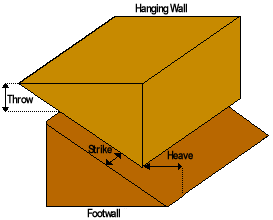
Figure 5: Fault nomenclature.
The strike is the horizontal distance moved. The throw is the vertical distance and the heave is the distance moved perpendicular to the fault.
The types of fault, with arrows showing motion, are shown below:
| Diagram | Name | Mode of Formation... |
|---|---|---|
 |
Normal Fault | Extension (tension) |
 |
Reverse Fault (or Thrust) | Compression |
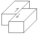 |
Strike Slip | Shear |
Faults rarely fall exactly into these categories, as they have some of the other types of motion as well, particularly some Strike Slip and rotational motion. Faults can also be reactivated, meaning a normal fault can be "reused" at a later time in a compressional regime. This produces complex drag folds along the side of a fault. Drag folds occur as the rock is bent due to the movement of the fault.
Conclusion
Structural geology is the study of the mechanics of rock and rock formations. Structures include folds, fault and dippigng strata. There are a lot of techniques used to study strucural geology includig measuring dip and strike (or dip direction) and stereonet projections. There are lots of terms used to describe both folds and faults, which not only describe the structure but imply some mode of formaiton.
References
C. Plummer, D. McGeary, 1997. Physical Geology.
C. Klein, C. Hurlbut, 1997. Manual of Mineralogy.
 GeologyRocks
 Send to friend